ICEINSPACE

|
GSO Dob Fan Project
Submitted: Wednesday, 30th May 2007 by Scott Tannehill
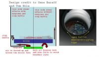
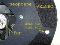
This describes my installation of a cooling and boundary-layer scrubbing fan on my Bintel™ 302 mm Dobsonian telescope. This is GSO Dobsonian marketed by Bintel. I live in the U.S., but I’m in Australia for a year with my family for professional reasons. While here I fully intended to exploit the fabulous southern sky, and I bought this 12” Dob for that reason. At first I didn’t plan to tinker on this GSO Dob – I’m only here for the year and I am likely to sell the thing before I move back to the U.S. But my tinkering tendencies triumphed over the just leave it alone inner voice. While my wife and daughter were away one long weekend I gathered supplies and installed three things: the fan and ring baffle (discussed herein); an encoder kit I purchased from Wildcard Innovations; and a mounting pole for my Argo Navis control unit which I had brought with me. (The latter two add-ons (encoders and the Argo pole) are mentioned only because you might see them in the photos and wonder how they relate to the fan project. They don’t. Also, I have replaced my collimation bolts with Bob’s Knobs to avoid the need for screwdrivers. That’s why the collimation bolts don’t look like GSO stock equipment.) I’ve installed fans (both front and rear) in my 18” Obsession back home and I can identify mild-to moderate improvement in image quality while looking at the planets. This improvement is most evident early on each night. Later – I presume after the mirror is closer to ambient temperature – turning off the fan has less immediate impact on image quality. I very much appreciated Gene Baraff’s and Tom Hole’s work and publications on this subject on the skyquest-telescopes Yahoo group. From them I poached the idea of using self-adhesive weather-stripping foam tape (from Clark Rubber) to create the ring baffle right above the mirror surface. This ring baffle is simply a circumferential baffle affixed to the inner tube just 1-1.5 cm above the mirror surface. I used several layers and the result was a baffle just 4-5 mm wider than the mirror. As illustrated in the diagram below, it redirects air blown up the from below toward the mirror, rather than letting the air follow its otherwise natural path up along the inside of the tube. This installation was very easy and took all of 20 minutes. Thanks again, Gene Baraff and Tom Hole for this elegant solution. One minor concern is whether my adhesive could give out on a cold night, but it’s soft and I can’t envision it hurting the mirror. If it falls off, I’ll remove the mirror and cell again and apply it using Loctite™ glue (superglue). And post an update. I would point out is that I have not confirmed whether this baffle’s location and exact shape are optimal and whether it couldn’t be improved. It isn’t as close as it could be to the mirror edge, and I don’t know the best height above the mirror surface. I had previously read Greer’s and Adler’s publications in S&T, and had a few exchanges with other veterans on various Yahoo forums on this subject. In addition to the fan mounting, and the ring baffle, I wanted to create a more-or-less “airtight” membrane on the back of the cell so air is forced out the top. Without such a large “air gasket” (or baffle, or shroud – I’ve heard all these terms used) much of the air bounces back and is re-circulated by the fan, reducing the total air movement up into the scope. See diagram. This is an old concept, discussed in prior publications, and well illustrated and discussed on the skyquest-telescopes, bigdob, obsession_users, and other Yahoo groups. While sealing the back of the tube like this is the worst thing you can do if you use passive cooling, it improve airflow if you use active cooling, increasing the total air movement for a given fan size and speed. I’m no physicist or air-management expert, but have a modest technical background and can draw some basic conclusions about the principles and it seems like a sound concept. One could argue the pros and cons of such airflow within the tube (eddy currents, etc). I would simply quote Greer’s study: it’s not airflow that degrades images but air of varying temperature within the light path. Here is a diagram of the air-flow concept, and a picture of my ring baffle from the front-tube side.
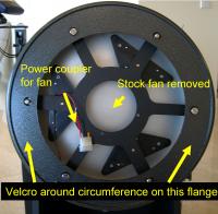
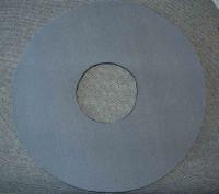
While I had the cell out to install this ring baffle, I removed the mirror (a necessary step) and removed the stock fan. (This is an 80mm fan that draws 0.16A and moves quite a bit of air. This is good for a fan designed to be used before but not during observing. It vibrates too much to use during observing, especially when it’s screwed right to the cell. Jupiter jiggles.) The Scythe fan was expensive at $30 AUD. Its 35 cfm rating was similar to the Nexus but it was significantly less vibratory. Its larger size permitted a lower rpm for a given air flow, and it was a higher quality fan in general. The cfm rating of the Scythe was more than adequate; reference Greer’s Part 2 article in June 2004 S&T wherein he suggests than anything over about 20 cfm is wasted air. I did add a fine mesh aluminum fan grate to protect fingers and catch any debris that might blow up. I wanted the fan to be easily removed and I did not want to drill or cut into the telescope. The most I wanted was removable adhesive. Following Adler’s article, I wanted to mount the fan on a vibration absorbing material. I settled on a Neoprene, which served the functions of mounting platform, vibration absorber, and air gasket (air baffle, air shroud, whatever term you want to use, etc). I bought some scrap Neoprene (cheap!) at Clark Rubber. I chose gray over the alternative offering of iridescent pink. Yep, it would have been a great topic of conversation at star parties. But I’m new to this country and trying to make some friends. A pink doily on the back of my telescope might complicate matters. [Clark Rubber is a great store by the way. They have so much cool stuff that I was trying to think up fun ways to exploit all the neat things I found there.]
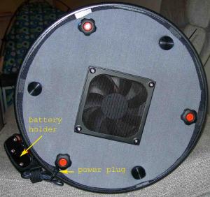
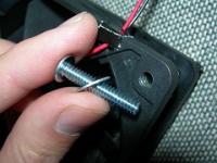
A power plug fitting came installed in the back of the cell. I kept that and the little 1.5V battery case that came with the scope. I cut the power wires on the old fan and spliced in the coupler (see photo) that came with my new fan. In this way, I can easily unplug the new fan anytime I want to remove the fan-gasket unit from the telescope. I cut the Neoprene to cover the back of the cell. I used a compass to mark and cut the circle. You’ll need a sharp scissors with the bolt connecting the two blades of the scissors tightened so there is some stiffness to working the blades. Otherwise it won’t cut the Neoprene clean. Most household scissors have been neglected in both these regards, by the way. Another very good option is a surgical-style straight scalpel blade with a sharp point. Hobby stores sell them. You can use this to make smooth straight or curved cuts. This works better than a scissors. With either tool, be ready to change blades or sharpen you scissors often, to keep the cutting smooth and easy. You can easily sharpen a scissors blade with a fine file; I used a fine circular rat-tail file I bought for a different project. I made the Neoprene a bit smaller than the cell-back deliberately, so it could stretch to fit without anything dangling beyond the tube edge. I designed this Neoprene membrane such that the fan case did not make contact with the cell or other metal components but is rather completely suspended by the Neoprene. This was important to prevent transmission of image-destroying vibration. The large size of this gasket improves the vibration dampening properties, and Velcro further reduces the vibration transmission. Don’t cut the center hole just yet (explained below).
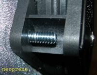
The fan is mounted to the Neoprene membrane using the existing holes in the fan housing. These are straight plastic holes about 3/16” diameter, meant to accommodate the self-tapping screws supplied with the fan. I did not use these original screws but rather choose 3/16” bolts about 15mm long. I used a very small awl to pierce the Neoprene and then pushed this bolt through. This is worth repeating: I didn’t cut a bolt hole in the Neoprene, I just used the awl-punch; the bolt pushes through just fine. A larger opening for the bolt might precipitate tear-through of the bolt head. These bolts conveniently do the same thing as the (unused) fan-mounting screws: they self-tap as you screw them into the fan case. I did not even need to use a nut on the other side, which was good because there is limited room for that. I did use a small 3/16” washer under the bolt head – Neoprene side – to reduce the risk of tear-through. This Neoprene is tough – hence its use in wetsuits – and I don’t think the bolts would pull through anyway. But there wasn’t any down side to using the washers. Cutting the central hole for the fan is tricky. Do not just cut a 12 cm circle. The Neoprene is stretched to fit and the hole cut needs to be smaller so when it stretches it doesn’t leave gaps beyond the fan housing; gaps will leak air. The center hole is more like 10 cm in diameter on un-stretched Neoprene and not perfectly circular. If you pursue this I suggest cutting this central hole out as the last step. First cut a much smaller 8 cm diameter hole first, mount the fan, and then stretch fit the Neoprene onto the tube so it’s in final position. Then, looking through the fan blades at the hole size and shape, you can decide how much (and where) to trim, a little at a time. This way you will get the right size. My opening is actually a bit less than 12 cm in the stretched condition and I have plenty of air movement. The Neoprene gasket – seems odd calling something 13” in diameter a gasket but I didn’t want to confuse it with the foam ring baffle above the mirror – stretches, obviously. To fit it just right I have to stretch the Neoprene a bit to get it on. That was deliberate. But if the Neoprene is too taut, it will transmit vibration more. Too loose, and it could (and did) sag and the fan could (and did) bulge down. Furthermore, when the fan is on it creates positive pressure, and it could (and did) force the fan further down, where it could (and did – almost!) collide with an encoder one might (and did) have placed on the azimuth bolt. A few trials with varying tautness identified the right degree of tension to prevent unsightly “fan bulge.”
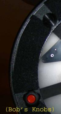
I designed the gasket so it was easy to apply correctly each time to accomplish this right degree of tension: I cut holes in the Neoprene where the collimation and locking bolts should fit through. So it’s easy to get the right tension and position by just lining up the holes in the Neoprene with the collimation and locking bolts on the back of the cell. There are some changes I’d make if I had to do it all again. I’d make my Neoprene a tad larger (you can see it’s undersized a touch) but not by much; otherwise you’ll have it extending beyond the tube edge! Another nuance involves my upgraded collimation knobs (Bob’s Knobs). I cut the holes in the Neoprene big enough for the bolt. But the Neoprene is a few mm thick and as such it comes into a little conflict with the much wider knobs if the bolt is screwed in all the way. I don’t think it’s a problem, but I’ll monitor this. If needed, I will cut out a U-shaped section of Neoprene to remove this issue, but I hesitate because that will change how the membrane fits on the back and maybe leak air. I’m still puzzling over the best way to mount the battery case; it’s stuck to the outer tube surface with Velcro now, acting as one of my counterweights. I don’t really have room inside the cell to store it. The supplied battery case that came with the telescope holds eight 1.5 volt AA batteries. The question then arises on how fast to run the fan. This Scythe fan actually runs fine on a 9V battery, and not to badly, but probably not as long, given the higher current draw than most 9V applications utilize. Using a 9V battery is one option to reduce vibration and the battery size problem. Another option is to use just 6V (four 1.5V AA batteries) which reduces the vibration even more. This is one more advantage to buying a premium low rpm fan: a lower start-up voltage. This Scythe started up and ran just fine at 6V, also. You’ll find many cheap higher rpm fans don’t even start up at lower-than-rated voltages. You have to give them a spin, like an old WWI fighter plane’s propeller, to get them going. Not practical, certainly, and you risk finger injury. With the fan operating even at 12V, I cannot detect any vibration at the eyepiece when doing a quasi-star test from my apartment rooftop patio. I cannot hear the fan unless I’m at a very quiet location and I put my ear up to the fan grate. That’s the bonus of spending $30 AUD on a computer fan, I guess. My Dob has a near-air tight front tube cover, and this cover has a small aperture mask built into it, with a removable cap, revealing an 8 cm aperture (hole). With only this 8 cm aperture opening and the fan on, the force off the airflow blows out a match. I conclude my air movement is sufficient. I did a simple experiment. I taped the fan without the gasket to the back of the mirror and there is barely detectable airflow out the front of the tube. With the gasket creating an airtight system this airflow is strong. The gasket is the only variable, so it really makes a difference. On high power high contrast views of planets (To all Northern Hemisphere folks, did you know that Jupiter is almost at zenith down here?) I notice improvement when the fan is operating and deterioration within moments of the fan being turned off, at least in the first 1 hour of observing each night. I keep my scope inside, and it’s colder now. I expect the benefits of boundary-layer scrubbing to be reduced as the mirror’s delta-T drops over time. But this mirror cooling can only be improved with this fan and air-management system. I’ll be the first to admit the modest benefit this modification imparts overall (mainly planets and the moon, when the mirror is still very warm relative to ambient), and for that reason might be considered a waste of time and money. You be the judge! There are many possible criticisms of this project, and an almost endless number of possible variations on this design theme. This is, after all, just another iteration of a prior design. Some might avoid this entire fiasco by simply putting a large box fan up against the back of their scope for 30-60 minutes before observing, to drive down the delta-T and reduce boundary layer issues. I do that, too, by the way. But I’m always fighting the clock. I rarely get to a site (even my rooftop) with much time to spare, and I rarely find myself with the luxury of an hour or two to wait for “thermal optimization.” Also, in Victoria, there is a fairly dramatic change in temperature as the night progresses, and your mirror will always – always! – lag behind ambient. A continuous fan can only help keep pace with this change in temperature. Anyone with questions, or to request more clarification or different pics, feel free to PM me on IceInSpace; member name Tannehill.  |
|
||||||||||||||||||||||||||||||||||||||||||||||||