ICEINSPACE

|
Argo Navis Stalk
Submitted: Wednesday, 30th May 2007 by Scott Tannehill
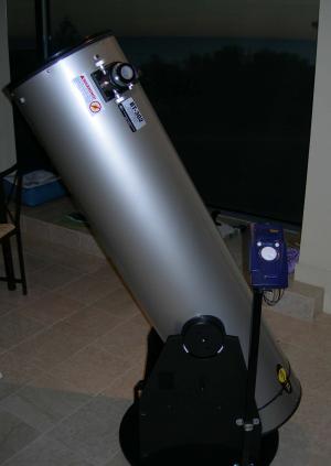
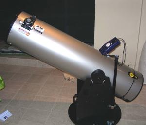
This describes my installation of an improvised support pole and platform for my Argo Navis DTC on my Bintel™ 302 mm Dobsonian telescope. This is GSO Dobsonian marketed by Bintel. I’m from the U.S. and here in Australia for one year. I own an 18” Obsession back home, and have the Argo Navis and ServoCAT control systems for GOTO and tracking functions. I bought this GSO Dob for the year here and installed encoders on it. I brought my Argo Navis control unit with me from the States. Wildcard Innovations – based in New South Wales – markets an encoder kit for this telescope, and installation of this kit took only about 20 minutes. There are always a few idiosyncrasies to any after-market modification, and the encoder installation was no different. There were minor azimuth and altitude encoder installation obstacles to overcome. Encoders are to be mounted at the precise center of the axis of rotation. The azimuth encoder bearing (that shiny metal cylindrical part jutting out of the black plastic case) drops into a central well bored into the center of the azimuth bolt. The altitude encoder bearing seats into a special bolt replacing one of the tension spring mounting bolts. These tension springs must mount at the altitude axis line, obviously. The bearing of the encoder moves with the axis in question. For the encoders to register this movement, the body of the encoder (the black box part) must be fixed. Thus introduces the so-called tangent arms or encoder arms, the fixed part of this assembly. In the case of this Wildcard kit, these are brass-like arms that connect the encoder body with a fixed point on the telescope. The azimuth encoder arm was intended to screw into the rocker bottom. Remember, the bearing is grub-screwed into the center bolt which is not itself fixed to the rocker bottom, but rather is fixed to the ground board underneath. The two spin about each other as part of the azimuth motion of the telescope. The altitude encoder arm was intended to be screwed to the side board of the rocker box. The problem was, not surprisingly, wood and particle board frames are not perfect. There was a little precession of the rocker box as the unit spun, resulting in a oscillating change in height of the rocker bottom under the azimuth encoder. I refit the azimuth bolt several times and experimented with slight shims under the az bolt flange. I couldn’t eliminate this precession. With this, if I screwed the azimuth encoder tangent arm down tight to the rocker bottom frame, it would bind more and more with each revolution and probably contribute to encoder errors or outright encoder malfunction and breakage. I needed to avoid fixing the encoder arm to the rocker bottom, but still prevent side-to-side motion or the encoder wouldn’t register accurately. My solution was to “fence in” the encoder arm. It can move up and down (float) to accommodate the changing rocker box height (from the encoder’s perspective), but still not move side to side. I did this with two thin screw-in hooks one might use to hand a picture. There is a picture of this hook below where I discuss the altitude encoder arm mounting method.
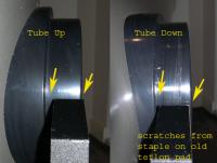
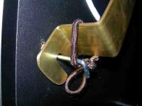
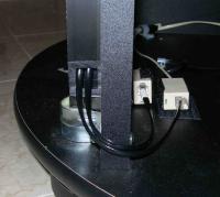
Next problem: when I depressed the telescope tube from zenith to horizon, the tube shifts 8 mm to one side. I presume the altitude bearing is not perfectly circular. In any event, the end result is that my encoder assembly – attached as it is to the altitude bearing – also moves 8 mm to the side. The photo above illustrates this shift. My solution was, again, to avoid screwing the encoder arm to the rocker box. This is actually the recommended technique for many telescopes, including the Obsession: don’t completely tighten either encoder arm, to account for such minor wiggling, although the 8mm shift noted here was more than most premium scopes would manifest. On the Obsession Yahoo group, I’d heard about not even screwing the altitude encoder arm down at all, but rather letting gravity hold it motionless. This worked great in my case. As the photo displays, a small hook (same as that used to “fence in” the az arm) catches the notch in the alt encoder arm; gravity holds it in one place. As the tube shifts left-to-right, the “floating” encoder arm moves with it (along the hook’s shaft) but not in such a way as to register rotary motion. You’ll note the small hair-bungee tied to the encoder. I thought this might be needed, but in fact, I don’t use it anymore. It just sits there without anything – other than gravity –holding it against screw-in hook other. I was just too lazy to take a new picture.
These two problems solved, I experimented with the Argo unit and it worked fine: I dialed in a dozen or so objects the first night on my patio roof and all were smack in the middle of my medium power eyepiece. I decided I’d be using the Argo often. I disliked on-tube mounting, and didn’t want to bend down almost to ground level to use it mounted on the rocker side panels. I wanted something akin to my Obsession back home, where I had ergonomic access to it from both a sitting and standing position. I considered buying the product (DSC Stalk) sold by StellarCAT and Markless Astronomics. I’ve seen GSO Dobs with this accessory. But I wanted something fast and cheap and I decided I’d just slap together an aluminum pole or rod using pipe-hanging brackets, and cable-tie the encoder cables to it. My only restriction was I needed something that could be easily removed each time because my vehicle wouldn’t accommodate anything much taller than the rocker box itself. I walked into Bunnings (the Australian equivalent of Home Depot for you Americans reading this) and wandered around. I found some square black-anodized aluminum tubing that looked promising. Called Connect-It, this brand consists of variable lengths of square aluminum tubing and plastic fittings that allow one to connect the tubes in many ways. This is illustrated at http://www.rcr.com.au/connect-it/. It’s easy to cut with a hacksaw. I bought two 90 cm lengths and ending up using just one. Other components: galvanized angle bracket (in the roofing section, not the “bracket” section), some flat brackets, shiny conduit clamps from the electrical aisle, and miscellaneous bolts and nuts (lock nuts) I had all I needed. I elected to use up some leftover Teflon to make it a rotating platform. First I’ll explain the lower section and stalk. Pictures help more than words.
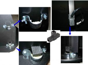
I cut a very short (just 4 cm long or so) length off the 90 cm tube. This was the receiving end for the long tube connector’s “male” end (described below). I secured this receiving end tube in semi-permanent fashion to the bottom of the rocker using one of the conduit clamps. This is the fixed base for the stalk is shown in the lower middle frame above. The conduit clamps are bolted to the rocker side panel, not screwed. This required drilling a hole through the entire thickness of the side panel, obviously. But even with a washer, the bolts do not protrude enough to risk collision with the tube. I wasn’t energized enough to want to pant them black or anything, but you could for a nicer appearance. I next cut the remaining tube down to 75 cm length. I used one of the plastic connectors on the bottom of the long pole but cut off one protruding right-angle end of the connector to permit the encoder cables to exit. You could have left that right angle section, but it didn’t serve any purpose. I filed away the plastic end of the connector on the stalk so it would easily slide in and back out of the fixed base. This is important, as these connectors are originally intended to connect the lengths of tube very tightly – i.e., permanently. To make it easy to remove, you need to file off the end of the plastic connector until the connector slides into the tubing with little or no effort.
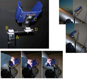
The top end of the stalk got a bit more complicated than I first intended. In the end, I used both an angle bracket (to mount the Argo) and a flat metal connector plate, and some Teflon and a few bolts and a lock nut to create a platform with two degrees of freedom. I can move and rotate the Argo to accommodate changes in position at the eyepiece. Again, pictures tell all (below).
I cut away one end of the top connector (A) to make it easy to exit out the cables and insert the center bolt. I drilled a hole in the top of the plastic connector (A). I then placed a sandwich of Teflon, a duct-tape wrapped flat metal plate, another Teflon pad, and then the bolt, a 3/16” one, with a lock nut on the end (B). Tightening this lock nut was the hardest part, as it is tucked inside the connector. But this allows the assembly to free rotate. The right angle bracket is bent to about 45 degrees (C), and has as similar Teflon sandwich (D). And the angle of the bracket angle is your choice. I experimented and decided this angle was the best balance for viewing and using the dials in the sitting and standing positions. It is strong metal, but I bent it some more with a boot on concrete (lacking a vise as I do).The duct tape is just to cushion those sharp metal edges. It doesn’t look pretty, I know, but neither do I…and I work just fine, too. Lastly, it’s worth noting that by luck the Argo cradle (C, blue plastic in picture) has mounting holes whose separation matched the right angle bracket perfectly. At Clark Rubber you can buy small rubber fittings to over exposed thread on bolts and screws. Those are the small black coverings over the bolts under the Argo cradle. To re-visit the stalk, one of the upper clamp bracket nuts is a wing nut, as the photos show if you look close. Loosen this and you can slide in the stalk and seat it into the fixed base, tighten down the wing nut, and the whole assembly is secured rock-solid to the mount. Loosen the wing nut, and the whole stalk slides up and off the base without trouble. Slide-in takes all of 15 seconds, and connecting (or disconnecting) the encoder cables takes all of 15 seconds, and sliding the Argo into the cradle and plugging in that upper encoder cable takes about 15 seconds. Total set-up time is less than 1 minute. You will need an encoder cable extension for this system. The encoder cable remains within the aluminum tube (threading it in was slightly hard but thankfully only done once), exiting as is shown from the top and the bottom. The top end plugs into the Argo as a RJ45 connector. It splits immediately into two RJ12 connectors, which feed into the stalk and exit from below. These cables stay in the stalk and therefore need to be unplugged from above and below each time. The az cable reaches my az encoder just fine. It’s just “around the corner” from the stalk base and the normal cables reach to the encoder (barely). But the alt end isn’t long enough for my alt encoder. I’ve mounted that encoder on the opposite side as the focuser and Argo/stalk so the cable needs to be about 2 meters long. I did this deliberately. The alt encoder is pretty much just hanging out there waiting to be bumped. On the opposite side it’s more isolated from the foot traffic on the action side of the telescope and less likely to be damaged. But too far away for the stock encoder cable to reach in this application. Important Fact: the Argo Navis uses non cross-over RJ12 cable. It’s also called Category 5 RJ12 cable. In contrast, phone use cross-over RJ12. If you connect a plain phone cable into the Argo Navis encoder line, it will not work. Nothing bad happens. Just, nothing happens. These are different cables and they don’t line up the same end to end. Non-cross-over RJ12 is harder to find and more expensive. If you are cheap but clever you can cut and re-splice a phone RJ12 into a non-cross-over RJ12. Buy some phone cable and an extra male-to-male RJ12 connector. Cut the cross-over RJ12 cable (phone cable). Strip all the wires on both ends. You’ll have 4 on each side: black, red, green, and yellow. Yellow may be white, by the way. Your instinct is to splice them black to black, green to green, etc. Instead splice: black to yellow; red to green; green to red; and yellow to black. It’s a mirror image of the way the wires ran in the cable, you’ll note. These are small wires and it takes patience, but it can be done in about 30 minutes. That’s why you might see a bundle of taped-up beige cable in my rocker bottom, tucked in the corner. Or you can buy these proper non-cross-over Category 5 RJ12 extension cables from Wildcard, or have them custom made by StellarCAT. But this makeshift cable works fine.
 |
|