ICEINSPACE

|
A Simple Polar Alignment Jig for a GEM Tripod
Submitted: Wednesday, 16th July 2008 by Trevor Hand
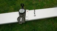
IntroductionWhilst polar alignment for photographic use needs to be very accurate (to within minutes of arc), alignment for visual use is not as critical. Simple alignment using a compass with allowance for the local magnetic deviation is sufficient for most purposes. To make setup quite easy, this simple jig allows alignment to a couple of degrees with minimal fuss. Total material cost, including all the timber, is about $10. If you have some suitable scraps of wood lying around in the shed the whole thing can be made for a couple of dollars and less than an hour of labour. AssemblyThe jig consists of a piece of wood that is long enough to span the distance between two legs of the tripod. Near the middle of the board, use a setsquare to mark a line across the timber. Then, using a protractor, mark a line that is to the right of the centre line by your local magnetic deviation (the value for your area can be found from many sites on the internet, eg. the deviation in Melbourne is approximately 11 to 12 degrees to the east). Cut a small piece of wood, something around 10mm square will suffice, and lay this along the angled line. Drill a couple of holes in the small block so you can screw it to the baseboard. Attach the block to the base with a couple of solid brass screws; be very careful that the screws you choose are not magnetic, many of the screws you may find at your local hardware store may be plated steel. I took my compass with me and moved the packet of screws over it to check it had no effect on the compass needle.
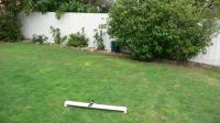
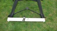
The next step is to screw two blocks on either end of the baseboard using more brass screws. This will ensure that any unevenness in the ground won’t allow the board to wobble. Finally, give the whole thing a couple of coats of paint; I had some white left over from renovations. I also painted a line parallel to the block to indicate the direction to magnetic south and a line perpendicular to the side of the baseboard to indicate true south. This makes it easier to picture how the jig works. UsageSimply place the jig on the ground and push the compass up to the block. Now turn the baseboard around until the compass is pointing north-south. The long side of the jig will now be the correct number of degrees off perpendicular to magnetic south and will be running exactly east-west.
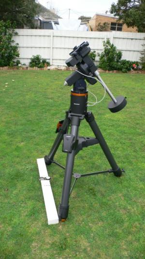
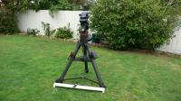
Simply place the tripod next to the jig. The “south” leg of the tripod is the one that it not resting against the jig. To keep it in place, I put one foot gently onto the jig and move one tripod leg up to one end and then gently rotate the other leg up to the side of the jig. You are now done. To create a jig for areas with different magnetic deviations, simply align the mounting block at the same angle as the local deviation. If the deviation is to the east, and most of Australia is, the line is to the right of perpendicular. If the deviation were to the west, as in some areas of Western Australia, the block would be to the left of perpendicular.
LimitationsTo get the best alignment using the jig, the centre line through the equatorial head will need to be perpendicular to the two legs used to align against the jig. If this is not at least reasonably close, the alignment will be out by this amount. Most mounts will have some sort of adjustment to swing the head in azimuth around the top of the mount. When using the jig you should be aware of any nearby iron objects. Reinforced concrete will cause alignment errors and will not allow the jig to be used, as the compass will be very close to the wire. In this case you will need to find an alternative method of alignment. The concrete viewing area used by the Mornington Peninsula Astronomical Society has the pad laid out magnetic north to south, so the stress relieving grooves in the concrete run directly north south. By placing the jig so that the small alignment block in aligned with the grooves, you will get the correct angle without the need for a compass at all. If your tripod does not have a “North” leg (as is usually termed in most instruction manuals, and becomes the “South” leg in the southern hemisphere) the alignment jig design will need to be altered appropriately. This design could be used as a basis for an alignment jig suitable for your tripod. Resources
Article by Trevor Hand (OneOfOne). Discuss this article on the IceInSpace Forum.
 |
|
||||||||||||||||||||||||||||||||||||