ICEINSPACE

|
To Build an Observatory
Submitted: Wednesday, 7th April 2010 by Dennis Greeve
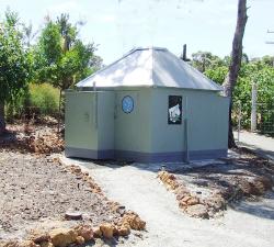
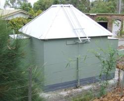
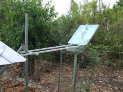
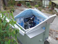
How many amateur astronomers have given thought to owning an observatory? After many hours of doddling with pencil and paper I settled on the final design which has proven to be a success. Admittedly I have sixty odd years of experience in the woodworking trade and own a well equiped workshop, but don't let that destroy your dream of building an observatory. It can be built with a minimum of hand tools at a reasonable cost . Let's start with two pictures of the completed observatory which houses a Meade LX90-8 inch telescope, Polar mounted on a self built fully adjustable wedge and a few add ons such as illuminated finder and remote focus.
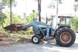
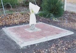
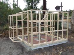
Musing over design, a number of factors dictated the final out come. A semi rural area with numerous trees and minimum yard space made it difficult, but how many amateur astronomers have the choice of an open paddock to build on! A sliding roof never impressed me and my first thoughts were centered on a rotating roof or a dome. Cost and the hours to construct killed that idea and the two pictures show the completed project. Just a few minutes to open up and close and its totally weather proof. My aged sight makes viewing in the norm difficult, whereras the webcam, DSLR camera and Laptop computer has made astronomy a completely new concept. I can sit in comfort at either annex desk and control the scope while partly under cover of the two roof sections that remain closed. Power is provided via a flex from the workshop, converted to 12 volt dc with a red light over each desk. The HBX, on an extension cable clips to the desk front for ease of telescope control. A retired farming neighbour kindly leveled the site with his front-end loader exposing the 60cm deep laterite layer - commomly known as Iron Stone - which covers the area just a few centermeters below the weathered surface and with great difficulty a 50 cm square hole 50cm deep was excavated for the concreted steel column and when set, brick paving was laid with the outer edge formed up for concrete edging.
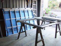
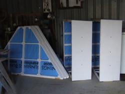
To hold the light construction down, 12mm dia holes were drilled into the laterite and 60 cm lengths of 12 mm dia steel rods driven into them. When the intitial errection of the wall frames were in place, steel plates were welded to the rods and screwed to the bottom wall plates. To minimize cost and keep everything within my ability to handle, I decided to make all the frame work ex 50mm x 25mm pine. I had access to non returnable pallets, which when broken down, sawn and dressed, would provide all the short trimming and only lengths 1.2m and longer would be purchased. Also all the wall and roof sheeting would be 3.5mm MDF cover sheets to the vinyl covered MDF board. These 2.4 m x 1.2 m sheets I could purchase at a reduced price and they dictated to the finished design and dimensions. To use these sheets in all weather conditions they required a number of oil base paint coats. One very important feature was to keep the wall sheeting well above the ground and a 20cm strip of colour bond steel was first fixed to the bottom of the wall frames with the sheeting overlapping the steel. The wall frames, which included the two annex, were made up on the workshop floor and assembled on the foundation, then returned to the workshop to be insulated and sheeted. All the sheeting was precut to size and given two coats of oil base undercoat to both faces with special attention to edges. Cad coated flat headed posi drive screws were used to fix sheeting and were sealed against moisture penetration with paint. The final painting was done after assembling. Walls received two coats of exterior acrylic and the roof two coats of exterior aluminium oil base enamel. Interior exposed framework was finished with one coat of white semi gloss acrylic.
Note the annex (one only shown) is above the floor line and the bottom plates which are treated for white ant protection are blocked off the brickwork for drainage and damp proofing. Although foil insulation is only rated 1.6 it has proven to be effective when the temperature is in the 30s. The four roof frames were later further insulated with styrene tiles cut from vegie cool storage styrene boxes, fitted and glued between the roof framing. The wall frames have a row of trimmers above the bottom plate to provide fixing of the 1.2m wall sheets where they lap the 2cm sheet steel strip, which inturn over laps the sheet steel forming to the foundation to provide good weathering.
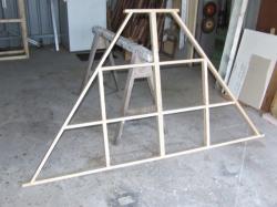
To back track a few months to the period of designing the observatory a small model was made of the roof to obtain the required angles and from these measurements the roof frames were constructed and sheeted.
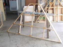
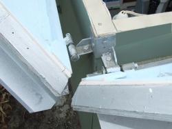
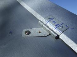
The basic roof frame has a 50 mm x 50 mm centre rafter for stability. To strengthen all the joints, 6 mm ply gussets were glued and pinned over each. Trimmed for size the frames were given a coat of white oil base undercoat and one finish coat of semi gloss acrylic paint. Insulation stapled down and sheeted with the prepared sheets. The over all roof frame height is 1.1m, which provides 10 cm over hang of the roof sheeting. This is evident in the pictures. With all the sections completed ready for assembling on the foundation, it required the steel roof pivots to be made. Two for each section of the roof were fabricated. One roof section was held in place with supports while measurements were taken and a pair of test pivots were made and fitted. The roof pivoted as planned and all the pivots were made to this pattern, which was nothing more than a two leaf butt hinge with adjustment to the leaf that is screwed to the wall frame.
The wall frames have ex 50 mm square corner studs providing fixing for the steel angle base plate for the slotted hinge supports. A lightly constructed open topped construction as this has no cross bracing to maintain the square and these angle base plates play an important part in the final adjustment to all four roof sections.
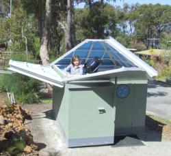
To be able to open any two of the adjoining roof sections, the ridge caps were required to be hinged and twelve special sheet metal hinges were made. The span of each roof frame was calculated to be no greater than the MDF sheet width 1.2 m. This provided a 40 cm opening in the roof apex, which required a square sheet metal cap to close it. When all the roof sections are closed and the four ridge caps folded down, the top cap locks the roof down. An easy method of removing the cap was required and although crude it works. Each roof section when opened rests on a simple single strut. The North/South struts fold down to prevent grandchildren being hurt while playing around the building. The East West struts are fixed. All four can be extended when a low viewing angle isn't required. Crude but effective. Note the two roof supports. The long strut is removable and the short one folds down when not in use.
Note the hinged ridge capping. Any one or two adjoining roof sections can be opened. The remaining sections are self supporting.
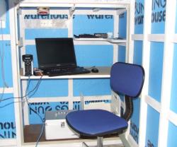
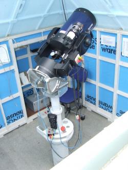
Finally this is what its all about. Nothing more than a cover for the telescope and the computer. The HBX and remote focus control beside the laptop. Note the red light above. The red lens can be moved to the side providing a white light. The battery pack and equipment holder on the support column is mounted on three bearings and rotates as required to prevent cable wrap around. Note the handles central to each roof section.
If any IceInSpace member admire the design and genuinely intend to build, I’d be more than happy to answer questions on the thread linked below. Article by Dennis Greeve (Dennis G). Discuss this article on the IceInSpace Forum.  |
|
||||||||||||||||||||||||||||||||||||||||||||||||||||||||||||||||||||||||||||||||||||||