ICEINSPACE

|
An Adjustable Illuminated Finderscope
Submitted: Monday, 5th July 2010 by Dennis Greeve
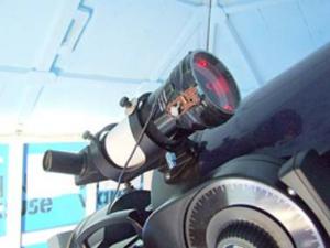
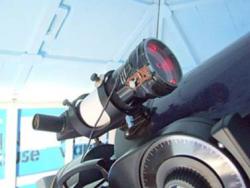
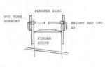
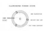
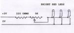
Before LEDs were invented, the early TV sets used an unusual method of providing a POWER ON indicator to the front of the cabinet. A rod of coloured Perspex with a small low voltage incandescent globe attached to the inner end transmitted the light through the Perspex to show as a coloured light. I copied this method to provide an illuminated field through which both the object and the cross hairs are viewed. The transmission of a red light placed edge on to a disc of Perspex fitted to the front of the Finder Scope provides an even soft pink glow over the disc enabling the cross hairs to be seen over the star, moon etc., without any loss of clarity to the image. To use this method of illumination, I designed a suitable push on support for the Perspex disc and three bright red LEDs using suitable PVC tubing. The Meade finder scope supplied with their telescope is a straight through design, which I find impossible to use with my age and inability to turn my head at odd angles. Having a 90 degree GSO finder scope of the same diameter, I swapped it for the Meade finder scope without any change to the Meade support bracket. A 30mm length of PVC tubing, close to the over all diameter of the finder scope, was bored to a sliding fit over the barrel and a similar length of the next larger tube size fitted over it and glued. This was drilled to provide a positive support for three bright red LEDs, which were inserted and taped over with black insulation tape. A rough disc of 3mm clear Perspex, with the paper protection to both sides, was bored central with a 6 mm drill to take a bolt, which was held in the lathe chuck and the disc turned to fit tight into the large dia tube. Three small notches file and polished smooth into the edge to fit over the red LEDs. The LX90 Scope is powered from a 12volt rechargeable lead acid battery via a power take off panel, providing the additional power for the Remote Focus and a 3volt reduction circuit to power the Finder Scope LEDs. An adjustable resister and one fixed resister is attached to the push on support, providing adjustment for the required degree of illumination.
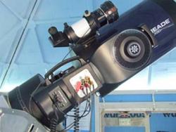
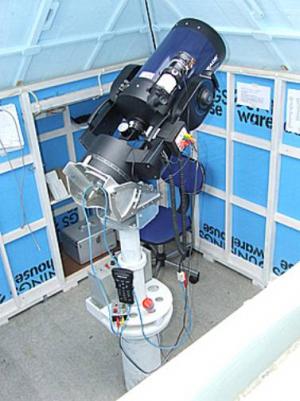
In the left image above, note the red glow transmitted through the Perspex edge to the opposite side from the LED under the adjustment circuit board and around the 6 mm hole central to the Perspex disc. All adding to the soft glow illuminating the cross hairs. In the image below, the power take off reduces the number of cables and provides a housing for the voltage reducer. The coiled cable supplied for the plastic LNT device (not used) has been utilised for the supply power cable. This arrangement combined with the rotating battery support helps to prevent cable wrap up.
The measurement between the object lens and the Perspex disc is not critical. I assume the illumination adjustment accommodates for this. I have not had to make change to the originals setting. The fixed resistor is a half watt and the 5k is a miniature pot mounted on a strip of Vero Board.
Article by Dennis Greeve (Dennis G). Discuss this article on the IceInSpace Forum.  |
|
|||||||||||||||||||||||||||||||||||||||||