ICEINSPACE

|
Fitting DSC's to a 16" Lightbridge
Submitted: Wednesday, 22nd September 2010 by Barry Gerdes
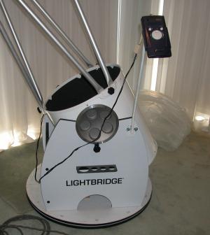
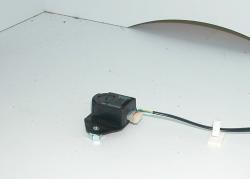
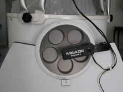
I had an old Meade Magellan 1 that I purchased on a whim from Meade when they were supplying Australia direct about 10 years ago and never used. I tried to sell it some time ago but the only taker who wanted it to fit a similar scope decided it would be too much bother and cancelled. I think he settled for an Argo Navis that came with suitable adaptors. I recently purchased a 16” Lightbridge telescope and as I still had the Magellan 1 I decided to adapt it to the telescope. I found most of the parts required very little modification. I was glad I hadn’t sold it. 1. The AZM EncoderThe modification here only involved removal of the old bolt and its retaining nut and replacing it with the one from the Magellan kit. However there is a positioning plastic sleeve that was too short to stay in the correct position so I made a longer one.
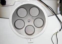
2. Alt. EncoderThis needed more work, as there was no suitable pivot pin in the center of the altitude bearing assembly. I took this off and put it in the lathe and drilled a 3/16” hole in the middle that I tapped out with ¼” Witt. I then made a pin out of a piece of steel tube machined to fit the encoder sleeve, opened the hole out and attached it to the altitude bearing with a suitable bolt and locking nut.
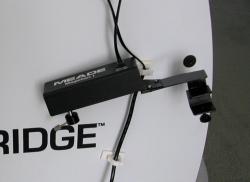
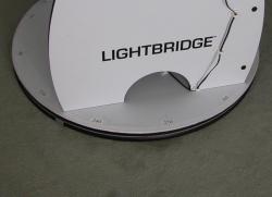
The Magellan altitude encoder assembly was made originally for a much smaller altitude bearing so with a hacksaw and hammer etc I cut the old retainer clamp off and extended its arm to suit the Lightbridge. I replaced the grub screw with a screw that could be adjusted with fingers to enable easier fitting and removal. I then made an altitude scale with AutoCad and pasted it on the bearing so I could test the Magellan on a dummy run. I did a similar scale for the azimuth that needed to be printed in sections. The skills I learnt in kindergarten in cutting and pasting came in very handy.
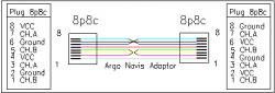
The Magellan while working OK needs to be reset each time the power is removed and the LED back lit screen was hard for me to read in the dark. I decided to try the Argo Navis as an alternative controller. The Magellan I connects to the encoders via a split cable plugged into the 8p8c connector on the side of the Magellan. The encoders are Hewlett Packard HEDM 5500 J06 4096 step. To save myself some money initially I decided to try to use the existing encoders and cable. The cable connections were known to be different so I designed an interface using an 8p8c in line connector to cross over the Ground and VCC leads. The signal leads were connected to the same pins. 3. Cable configuration |
||||||||||||||||||||||||||||||||||||||||||||||||||||||||||||||||||||||||||||||||||||||||||||||||||||||||||||
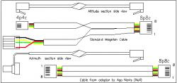 |  |
Click to Enlarge Fig 1 - Magellan 1 encoder cable |
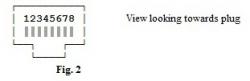
Click to Enlarge Fig 2 - View looking towards the plug |
| Magellan | Argo Navis | |||
| #8 | VCC | Altitude | Pin #6 | VCC |
| #7 | Channel A | Pin #7 | Channel A | |
| #6 | Ground | Pin #8 | Ground | |
| #5 | Channel B | Pin #5 | Channel B | |
| #4 | VCC | Azimuth | Pin #2 | VCC |
| #3 | Channel A | Pin #3 | Channel A | |
| #2 | Ground | Pin #4 | Ground | |
| #1 | Channel B | Pin #1 | Channel B |
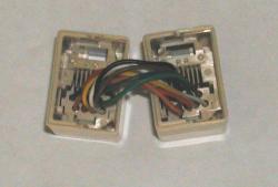 |  | |
Click to Enlarge Fig 3 - In line connector opened up |
Click to Enlarge Fig 4 - Adaptor connector rewired for Argo Navis (Magellan on LEFT, AN on RIGHT) |
|
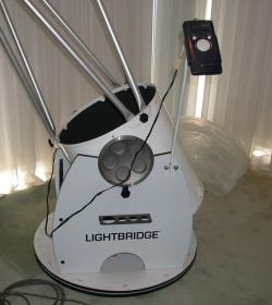 | 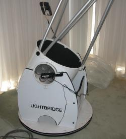 | |
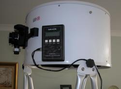
Click to Enlarge Lightbridge Stalk and Argo Navis |
Click to Enlarge Lightbridge Stalk and Argo Navis |
|

Advertisement  |
Advertisement  |
Advertisement |