ICEINSPACE

|
Illuminated Finder
Submitted: Tuesday, 10th April 2007 by Dennis Greeve
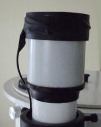
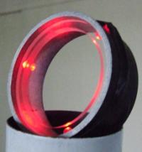
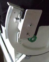
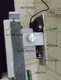
My first attempt to capture Saturn was extremely frustrating. Unable to see the cross hairs in the finder scope and guessing centre was a hit and miss effort. There had to be a better method and having read Mike Salway’s description of illuminating the scope with 3 red globes and a quantity of blue tack, it was worth a try. Red globes were not available and I used 3 bright red leds. Red leds do not drain as much out of batteries as globes and their light out-put is easy controlled, but their lens effect focuses the light forward whereas the incandescent globes scatters the light over the finder’s object lens. The required scattering is provided with a 6 mm wide x 5mm thick clear Perspex reflector ring sitting on the projecting leds. The inner dia of the reflector is no greater than the O/a dia of the finder aperture. See pics below. It so happened that the o/a dia of the finder scope is identical to the inside dia of standard 65 mm PVC tubing which slides over the scope without any slop. A 25 mm length was cut and the ends sanded smooth and 3 equally spaced 4.5 mm holes drilled 15 mm from what will become the top of the PVC ring to take the leds. A push fit. Note. Although the work sheet that comes with each bright red led purchased from Dick Smith Stores show the O/d as 5 mm they will fit tight into 4.5 mm hole if drilled without fist using a pilot hole and should they be found too tight the hole can be reamed or re-drilled. Leds require correct polarity- Globes do not- the long leg is positive + and the short is negative – Also the leds will blow if the voltage is too high. As Mike writes, the illumination is not over bright so it is best when wiring the circuit to add a fixed ¼ watt resistor right from the beginning of wiring. I used a 1.0k ohm resistor, but this can be increased if found too bright. The 3 leds are wired in parallel, that is, all 3 leds see the same voltage. Using 2 x 1.5 volt batteries = 3 volts. The voltage across each led must not exceed 2 volts. If you are purchasing resistors, they only cost cents, buy one at 1.0k another 1.5k and a third 1.7k all ¼ watt and use the one that suits your finder scope. A small toggle switch is required and a few short lengths of thin PVC covered hook-up wire. Join all the positive legs using red wiring and join all the negative legs using black wiring. This will prevent mixing the polarity. Leds will not work if wired wrong polarity. At one positive & one negative leg, solder a length of twin wire cable that is marked, so you know which is positive. I used a 2 mm dia coax cable, using the inner wire as positive and the shield as negative –no mix-up using this cable. The small control panel that holds the twin plastic battery holder, the switch and the resistor, was far too heavy to attach to the upper section of my Dob scope. What with a Telrad and a finder scope there’s enough unwanted weight, which requires balancing, so I clamped the panel down on the side of the altitude bearing and dropped the length of coax cable to it. If the illumination rig is not required, it all lifts off without any fuss. If the rig removes the guesswork out of getting the object onto the computer screen then the few dollars it cost is well worth it and I thank Mike for his idea. Wiring the circuit detail.The positive wire, common to the three leds is soldered to the resistor, which is soldered to the central switch terminal. The battery holder will require a snap on wired clip. These clips are made to fit 9 volt batteries and twin cell plastic 3 volt battery holders. Check the polarity and solder the positive lead from this clip to the outer switch terminal (either one) the negative clip lead is soldered to the black negative wire from the leds. The worst that can happen if you mix the polarity is the leds won’t work. Good viewing!
 |
|
|||||||||||||||||||||||||||||